HTM Compliant Hospital Quality AHU
This Range of MEDSAFE Cold Bridge Free Air Handling Units is specifically designed for use in the healthcare and pharmaceutical industry where high standards of cleanliness and sterile cleanable surfaces are required. Each air handling unit for this class of environments is compliant with HTM 03-01 22nd June 2021, NHS Specifications also to BS1886 Air handling unit performance specification.
It must be noted that HTM 03-01 specialised ventilation for healthcare buildings has been revised and issued on 22nd June 2021 for advice and guidance on the legal requirements, design implications, maintenance, and operation of specialised ventilation such as air handling plant.
Healthcare technical memorandum 03-01 (2021) supersedes all previous versions of HTM (2007), 2025 (1994) and DV4 (1983).
Part A Design and validation
Part B Operational management and performance verification
Note that the guidance contained in HTM-03 (June 2021) Part “A” applies to “new installations” and “major refurbishments” of existing installations.
For more information or professional advice and assistance please contact us on 0161 745 8888
To view our product brochure Click Here
Air Handling Units
.jpg)
.jpg)
.jpg)
Thermal Transmittance Class T2
Thermal Bridge Class TB2
Deflection
Class D2
Factory Air Tightness Class L2
Test Pre Delivery
Air Tightness Class L2
Filter Frame Bypass Section 7
Supply & Extract intake & Discharge Isolation Dampers - C3 Flow Loss (BS 1751)
Medsafe AHU’s can be configured as follows: -
1. Horizontal
2. Linear single or double stacked
3.Cabinet type units (supply & extract) the fans must be located on the bottom deck where possible to make it easier and safer to change.
The revised HTM-03 (June 2021) shows a preference to using direct driven electronically communicated (EC) fans where possible. Multi fans or fan walls can be employed to offer better capacity and resilience if a fan fails. Gravity or motorised dampers are to be used to prevent air recycle via the non-operational fan.
If the capacity flow rate is above a multi fan wall arrangement being used, then direct driven inverter plug fans can be used. The inverter is to be externally mounted outside the air stream.
Fan motors must have thermal cut out protection
Fans on AHU's serving critical areas must have maximum time of 20 minutes for change.
Medsafe air handling units do not contain belt driven fans.
Supply fans on Medsafe air handling units are positioned to blow through cooling coils and humidifiers to ensure drains will be under positive pressure.
When two or more fans are fitted into a fan wall we select where possible fans running in parallel. In case of fan failure, the remaining fan(s) should provide at least 80% of the design output where possible.
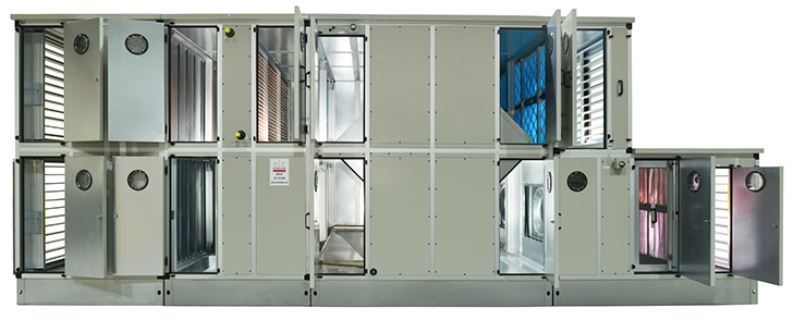
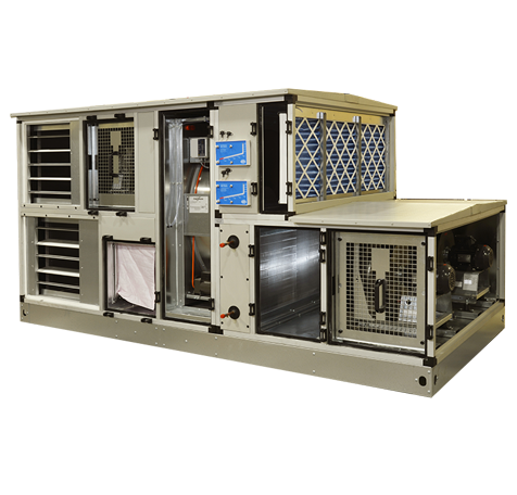
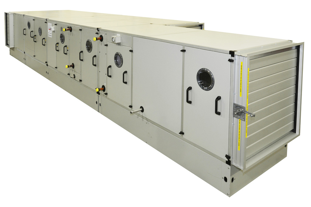
Typical Medsafe HTM compliant Air handlers Northern Ltd air handling unit construction and components are detailed below with photographs showing the construction and material used to provide sterile and cleanable compliance.
Within Medsafe HTM hospital quality air handling units dampers are used for shut off purposed with either motorised or manual quadrants. In the case of modulating dampers an appropriate modulating actuator is used. All dampers can be supplied to suit the function they are required to perform, therefore it is required that the correct information is passed when making a sales enquiry.
Damper construction will always be with low leakage BS EN 1751 C3 Flow loss, and dampers will have edge and blade seals to offer seal compliance. Blades will be aerofoil in shape to reduce pressure drop across the face, use cog wheels to reduce friction and torque on the actuator. Please note the cog wheels will be outside of airstream and contained in a fully enclosed housing to prevent any ingress of dust, dirt or atmospheric objects from damaging the cog mechanism.
Material of construction for dampers can be either anodised aluminium or stainless steel. Normally control or shut off dampers are constructed from anodised aluminium profile, but for cases where the dampers are isolating components such as coils or humidifiers etc which are subject to vigorous cleaning with aggressive cleaning materials, then stainless steel dampers may be more appropriate. Painted galvanised dampers can be offered for internal mounted dampers.
Plastics are not used in the construction of Medsafe air handling units either in the recuperator construction or damper face/bypass construction. Shut off Dampers externally mounted on air handling units with weatherproof construction will be manufactured from galvanised steel similar to the ductwork.
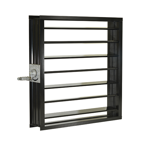 Epoxy Coated Option
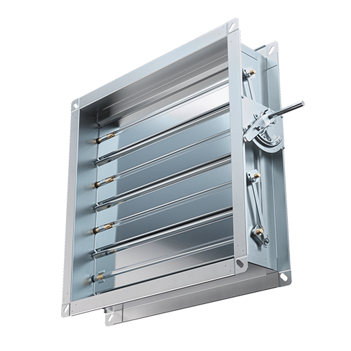 Standard Anodised Aluminium
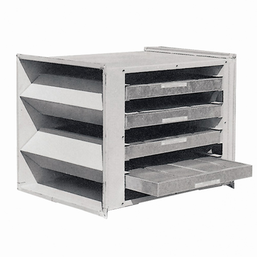
We use high quality panel filters of the pleated style to give higher dust loading capacity and lower resistance to airflow. These filters are often used as pre filtration to increase the life of secondary or final filters by reducing both particular matter and modular contamination.
Medsafe units contain 50mm deep pleated panel type filters to PM10.
Panel filters are held in a purpose made frame which is sealed for air bypass to section 7 BS EN 1886, filter panels are fitted into the frame and arranged for side or front withdrawal dependant on space and access availability.
For Healthcare Society’s (2018) SVHSoc.02 – ‘Change in air filter test and classification standards’
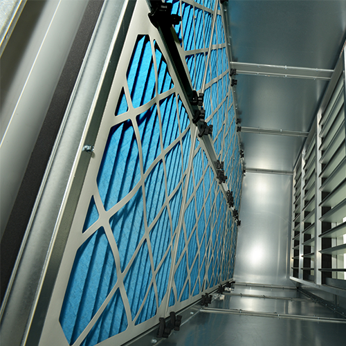 EU4 Grade Panel Filter Section
Frost coils can act also as a pre heat coil, coils are contained within the air handling unit on slide rails for ease of removal. The coil will be constructed from finless plain copper tubes with copper return bends and headers all cased in a powder coated galvanised sheet metal casework or stainless steel.
Access sections will be provided both sides of the frost coils
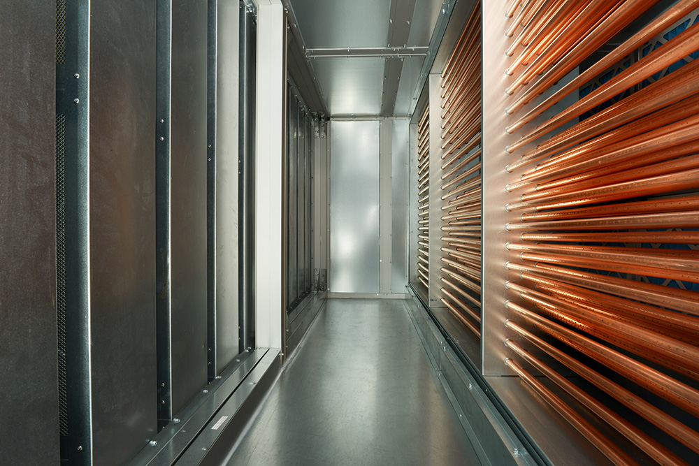 Finless Frost Coil with access and a attenuator section
To comply with energy related products (ERP) Directive 2018 for air handling units with supply and extract from the building being served. The European directive dated 1st January 2018 stipulates the following minimum energy recovery efficiencies, based on equal airflow.
Heat recovery devices with intermediary medium 68%
Plate exchanger and thermal rotary recovery wheels 73%
Air handlers northern Ltd can provide advice on all forms of energy recovery and explain the energy related product (ERP) Compliance for any project call 0044161 745 8888 and ask for sales.
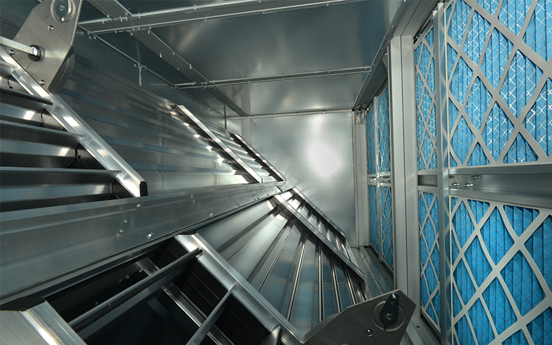
Energy Recovery system 1 (Plate Heat Exchanger)
The plate heat exchanger also known as the recuperator, has sealed plates constructed from aluminium allowing the supply air to cross flow with the extract air without any cross contamination.
Crossflow plate exchangers can take airflows up to 30m3/sec with ERP 2018 compliance, but they will dictate the size and weight of the air handling unit.
Special coating systems on the plate heat exchanger construction are available for coastal and hygiene applications, the type of coating will be dictated by the level of protection. A different plate exchanger is also available offering higher efficiencies of up to 85% recovery, this system is called a counterflow plate heat exchanger. It has a longer plate length with a different airflow configuration.
The counterflow air handling unit system is normally much lower airflows up to 2.5m3/sec.
It must be understood that the selection of the plate heat exchanger recovery device must consider pressure drop through the device as this will influence on the specific fan power of the air handling unit.
Plate heat exchanger devices will develop moisture on the exhaust side of the device, hence they will need to have a stainless steel drain tray with a 1:20 slope to drain the condensation created.
The section with the drain tray will need to have a full-size access section with stainless steel lining to allow cleaning to be done.
It is common practise to fit a double skin sealed porthole in the access section with a low voltage LED inspection bulkhead light.
Plate heat exchanger will be fitted with face and bypass dampers to allow for summer bypass of the fresh air. The aerofoil dampers will be arranged to allow for open/close positions of the bypass to give summer/winter operation and modulating control if required. Face and Bypass dampers will be epoxy coated with no plastic content.
 Typical Medsafe air handling unit with plate heat exchanger energy recovery device
 Face and Bypass Dampers
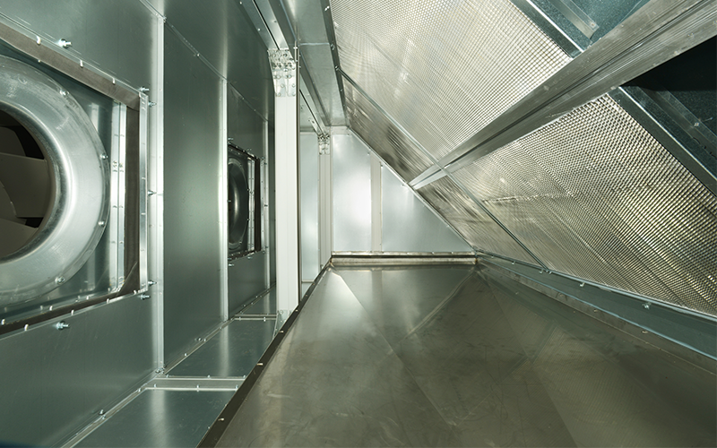 Fan Section with PHE
 HTM-03 Complient HRU with counterflow PHX
Electric Heating coil sections
All electric heating coils will be held within the air handling unit as stab in arrangement with integral terminal box containing element and cable terminations, the assembly is designed for ease of removal. Access sections must be provided to clean and inspect elements, which will be sheathed.
Each element consists of a nickel/ chrome resistance wire, spirally wound, insulated by compacted magnesium oxide powder and fitted within an incoloy AIS1321 titanium stabilised tube. The connection bushes of each element are brass crimped on each end.
Elements are return bent and mounted into the terminal box with airtight brass fixings glands and insulating washers. Heaters are designed to have an element surface temperature of 400°C at an air velocity of 2m/sec.
Please Note we recommend a minimum face velocity across the elements of 3m/sec to reduce the surface temperature and element glow, this is achieved by reducing the size of the casework containing the heating elements.
Terminal housings are manufactured from 1.2mm powder coated steel and conform to IPO40. Conduit holes and earth studs provided for cable entry. Bus bars are fitted with elements connected to give the correct operating voltage/stages/phase connection. Below we have given our recommended voltage / phase sizing.
Single phase: 220/240V / 1 / 50hz max 9 kW
Three phase: 380/440V / 3 / 50hz max 210 kW
In selecting the elements it is important to tell our sales department if the heater is to be controlled by :-
- On/off
- Staged control
- Thyristor control (modulating)
This will enable our technical sales department to configure the best element arrangement for the heater.
Testing
All elements are hot flash tested before fitting into the heater casing. They are then tested as a complete unit prior to installation into the air handling unit.
IMPORTNANT NOTE
- An Airflow switch must be fitted into the system containing the electric heater. This will turn the air handling unit off in case of airflow failure.
- A fan run on timer must also be fitted into the control system to allow the fan to run on to evacuate the heat off the elements.
High temperature cut out
Air Handlers Northern Ltd electric heaters all include a high temperature re-settable cut out switch arrangement.
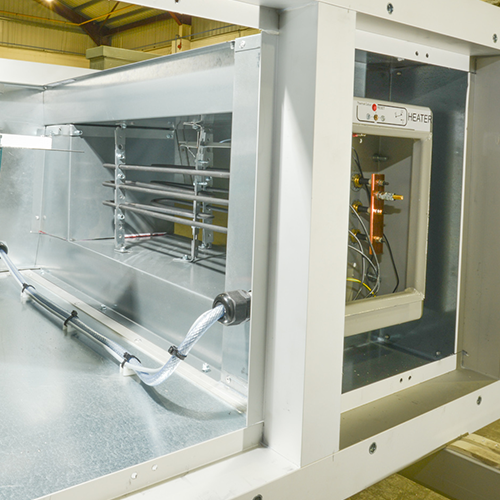
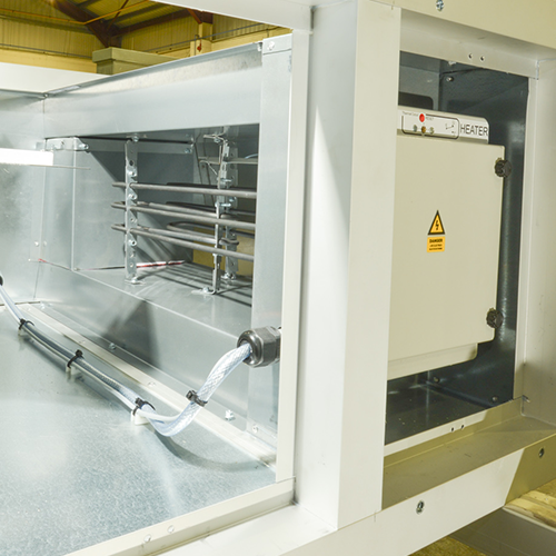
Electric heating coil with connection terminal box open and closed
Heating coils are cartridge style and contained within the air handling unit on slide rails for ease of removal. Coils are compliant with HTM specifications including airflow performance and construction /manufacturing standards.Access to both sides of the heating coil are provided.
Coil fin blocks are constructed from copper tubes. Headers and return bends with copper plate fins with self-spacing collars. The fin block is cased in a galvanised sheet steel casework to give a stable free-standing coil.
Other material of constructions are available which offer corrosion protection and enhance the coil life expectancy.
- Copper tubes with copper fins
- Casework for coil constructed from stainless steel.
Coil construction must take care of the atmospheric conditions entering the air handling unit, particular care must be taken when the air handling unit is subject to coastal locations.
Maximum face velocity for heating coils is 2.0 m/sec with particular note of the resistance to airflow which can influence the specific fan power calculation.
Energy Recovery System 2 – Run around coils
Run around coil systems are used when the supply airflow passes through an air handling unit designated as supply only. The extract system can be an extract air handling unit or a duct fan arrangement.
The supply and extract systems may be a distance from each other which may suit some schemes which have remote extract.
The term run around refers to the heat reclaim medium which is pumped around the circuit between the two coils. The coil on the extract side reclaims temperature from the room prior to exhausting it to atmosphere hence passing the reclaimed heat to the exhaust run around coil.
The fluid low grade heating medium passes the reclaimed heat to the supply side run around coil which transfers the heat recovered to the supply air.
It is common practice to filter the air prior to entering the exhaust run around coil. The same applies to the supply side run around coil provided it is not used as a frost protection coil which then must be plain bare tube construction with no fins.
Exhaust run around coils will shed condensate therefor must be considered as a cooling coil using the same hygiene standards with a removable stainless steel drain trays and 20:1 slope.
The casework containing the exhaust run around coil will need to have cleaning access with stainless steel lining to comply to HTM-03. Please refer to the cooling specification in this product document.
It is normal for the run around system to have a pressurised pumped system circulating the low grade recovery media between the supply and extract coil. It must be noted that high level auto air vents must be positioned at all high points in the system to prevent air locks.
Should you have any questions on a particular project and wish to seek advice call our sales team on +44161 745 8888
Energy Recovery System 3 – Thermal Rotary Wheels
Thermal Rotary Wheel energy recovery devices are only used for general areas with low sterile/cleanliness classification they are not recommended for high classification use.
The rotary thermal wheel revolves passing the recovered energy from the exhaust and transmits it to the supply incoming air.
Rotary Thermal Wheels have one disadvantage over energy recovery systems 1 & 2, due to there being a small amount of mixing incoming and outgoing air called purging, This can be reduced by using seals and brushes but by the nature of mixing can not be used for many hospital areas.
The advantage of a thermal wheel in general low sterile areas is the high thermal transfer efficiency, which can compare to a counterflow plate heat exchanger with a lower cross section and length of air handling unit.
- Condensation Wheels
These products only transfer moisture in the winter when moisture in the extract air condenses in the storage mass. They are best suited for use in ventilation systems without mechanical cooling. Different types of heat transfer foil are available to protect against corrosion on such as coastal location. - Enthalpy wheels
This type of thermal wheel is more commonly known as a hygroscopic wheel, the surface of this rotor supports humidity transfer. This thermal wheel is generally used in comfort ventilation systems to recover humidity during winter periods. - Enthalpy / Sorption Wheels
Thermal wheels of this type have high performance desicant coatings of the rotor. They provide a maximum humidity transfer capacity for minimal carry over. The high humidity efficiency is constant through out all climate conditions. Sorption wheels are especially designed for summer season cooling recovery and de humidification of supply air.
Some thermal wheels can be manufactured with epoxy coated rotors and casework to protect against coastal environment corrosion.
 External AHU with thermal wheel
 Thermal wheel
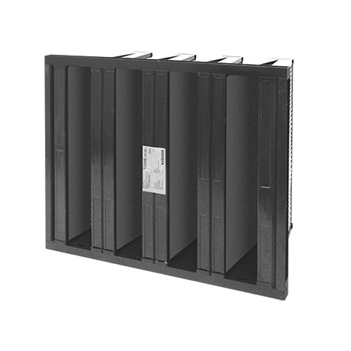
Bag Filters used in Medsafe hospital HTM-03 (2021) quality air handling units are of the multi pocket type and can be used as secondary or final filtration. Compact filters are used as a preference to prevent incorrect orientation or damage when changed.
The filtration media used to form the pockets is synthetic fibre and varies in length from 315mm to 900mm. Secondary or final bag filters must be installed on the positive pressure side of the fan.
The filters will be arranged in a holding frame having leakage C3 Flow loss to BS1751 with sufficient strength to not distort or bend. Air leakage past the filter frame must be sealed. The bag filters must be held onto the frame with purpose made fixings to keep the frame sealed against air leakage.
An access section must be provided to allow filter changing, the access section must incorporate a viewing port and LED IP55 light to inspect the filter condition while in operation.
In general the filter length is sized on a 1.75m/sec filter media face velocity and have a good dust loading capacity.
BAG FILTER GRADES :
PM2.5 Medium Filters – Remove 50 to 95% of 2.5 μm particles compact filter
PM1 Fine Filters – Remove 50 to 95% of 1 μm particles
For Healthcare Society’s (2018) SVHSoc.02 – ‘Change in air filter test and classification standards’
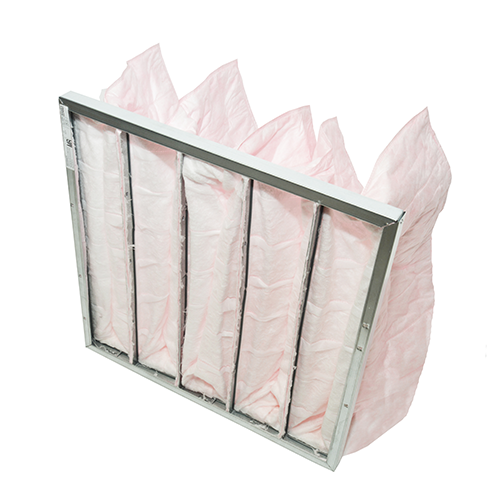 Typical multi pocket bag filter
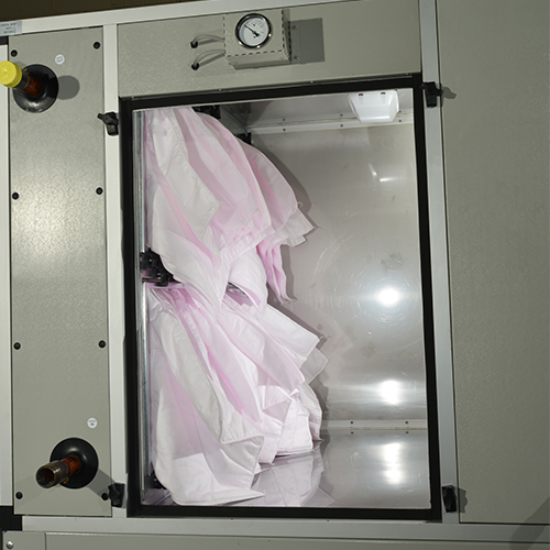 HTM-3 bag filter section
It is preferred by HTM-03 that filter condition indication is performed by a magnahelic type differential gauge rather than a inclined gauge manometer.
Also most control systems use differential pressure sensors set to indicate when dirty filters are reached. This applies to all types of filtration system used in the air handling unit.
The selection of the fan type will dictate the fan section configuration, these options are listed below.
- Plug/plenum fan selected, this fan type can have centrifugal or radial flow impellors. EC motors are direct drive coupled directly to the fan impellor, it is not recommended to have spare motors as requested in HTM-03, due to the re-balancing of the fan after the motor has been changed. To comply to HTM-03 requirement a complete fan assembly for each type of fan size should be kept as a spare.
It is also possible to provide duty and standby fan sections which isolate the non-operational fan, also with the use of non-return dampers or actuator operated shut-off dampers, auto changeover of the fans can be provided.
All fan selections are subject to ERP 2018 compliance with the required specific fan power. To comply with safety requirements of HTM-03 all fan selections must have lockable access doors with the warning labels fitted to the fan section access door. The section will have a viewing port and LED low voltage bulkhead lighting to inspect the fan in operation.
To prevent the transmission of vibration, each fan will be fitted with anti-vibration mounts with a minimum transmission loss of 95% and a minimum 20mm deflection. Flexible connections used will be flame retardant and of appropriate length to prevent vibration transmission to isolate the fan assembly from the air handling unit casework.
Fan guards are a HT-03 requirement and are fitted to all fan sections, in case of plenum plug fans this will be a fan door guard which allows fan operation for run inspection with full guarding for the operative making the visual inspection. Intake guards are also fitted. This also applies to motor out of airstream options.
Fan selections incorporate either a 10% increase in airflow or a 15% increase in pressure. Impellers are to be aerofoil profile and non-overloading.
Motors
The most common fan used in hospital air handling units are plenum type plug fans which are direct driven by an E.C. (electronically commuted) Motors with efficiencies of IE5 and have a 30% year on year energy saving over conventional AC motor drives.
For larger fans, belt driven fans, inverter driven AC motors are provided with IE2/3 efficiencies. The motor efficiency just like the fan efficiency is very important in reducing specific fan power.
EC Fans are controlled by most commercially available controllers found in air handling unit control panels, which vary the 0<10 volt signal to the motor. Conventional inverters operate differently and are often remote from the control panel.
All motors must have thermistors fitted and lockout relay, to give motor winding protection.
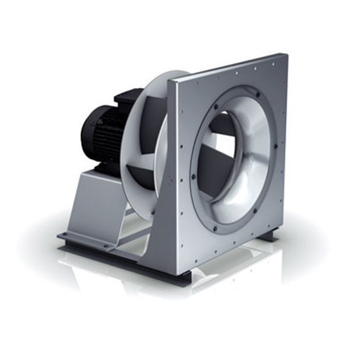 Typical plug fan
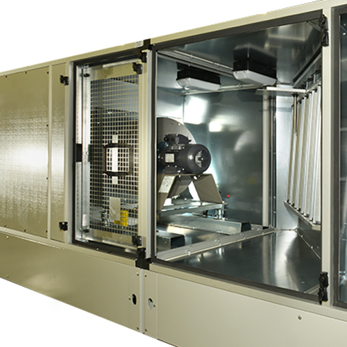 HTM-03 fan section
It is essential that in the design of cooling coil sections extreme attention is made to give cleaning of the coil, drain-trays and eliminators to the highest hygiene standards. The section is fully stainless steel lined with smooth edges and no areas which are not easy accesses to clean.
Drain trays under the cooling coil and eliminators are to be fully removable for cleaning and will have a minimum 1:20 slope designed to evacuate condensation from the coil and moisture eliminators.
A suitably sized drain connection is provided and placed in a position in the drain tray to completely remove all condensation.
All cooling coils must be positioned upstream of supply fans to create a positive pressure on the coil to put the drain tray and drainage trap under positive pressure.
Sizing of drainage trap heights is always provided on Air Handlers Northern drawings together with the base frame height. Care must be taken by the contractor to provide the correct glass trap and suitably sized drainage pipework with a good drainage slope.
Eliminators are a requirement of HTM-03 2021 to remove any moisture carry over from the coil and will be a suitable depth and profile to trap any moisture carry over and have protected drainage channels to make sure the condensate runs into the drain tray below.
Where cooling coil face velocities exceed 2.0 m/sec eliminators will be provided.
Eliminator blades can be 100mm/150mm deep depending on the water quantity to be removed, also will have 3 to 5 direction changes. Air Handlers Northern Ltd air handling unit software will automatically select the appropriate eliminator for the application of each cooling coil.
Cooling coils are selected with a maximum face velocity of 2.0m/s to comply with HTM-03, this will allow good condensate drainage from the cooling coil face with little or no moisture carry over off the coil face.
Eliminators and cooling coil casework will be constructed from stainless steel. Removable cooling coil drain trays are also constructed from stainless steel.
Cooling coil fin blocks are constructed in accordance with HTM-03 2021 and have copper tubes, return bends and headers with mechanically expanded copper fins electro-tinned, an alternative is allowed which can be used at the discretion of the design engineer or NHS Trust engineer, this option involves using epoxy coated aluminium fin material in place of copper fin material.
Care must be taken in the cooling coil section to keep the overall airside pressure drop to a minimum to reduce the total fan static pressure to within specific fan power ERP limits. We also recommend a maximum hydraulic pressure drop through the coil of 30 kPa again to reduce pump absorbed motor power.
To allow inspection of the cooling coil and eliminators also clean the surface areas, access sections need to be included in the air handling unit up and down stream of the cooling coil with full size access doors.
The access sections will have viewing ports with low voltage LED bulkhead lights.
To allow for ease of cleaning eliminator banks they will have to be removable eliminator modules, the modules can be single or multiple to reduce the weight for the cleaning operative. Grab handles which are staggered so they are not close together making it difficult to hold when removing the module are fitted on the front face. After eliminator removal it will be very easy to clean both sides of the cooling coil faces. Eliminator modules will be firmly held within the stainless steel holding frame with quick release fixings.
It should be noted that run around exhaust coils must be treated as a cooling coil with exactly the same design and construction as chilled water, direct expansion, heat pump supply side cooling coils. This note is cross referenced in the runaround coil section.
All cooling coil types are held within the air handling unit on slide rails for ease of removal, slide rails and blanking are constructed from stainless steel.
Cooling coil types
- Chilled water cooling coils have coil connections with air vent and drain connections fitted. Fin blocks normally have minimum 2.5mm fin spacing to maintain the lowest air pressure drop.
- 2. Direct expansion cooling coils are constructed as refrigeration coils for use with low GWP refrigerants, coil connections are sealed by the manufacturer after internal coil sealing and cleaning. After the refrigeration contractor has completed the pipework and coil internals will need rigorous cleaning and vacuuming out to ensure the compressors on the condenser or heat pump are not damaged. Heat pump supply side coils are constructed the same as direct expansion coils. To enable fin block decontamination and prevent damage during cleaning minimum 2.5mm fin spacing will be used on cooling coils. The fins will be a minimum thickness of 0.25mm..
Direct Expansion coils to be provided with the gas circuits split to allow 10% turndown of the nominal capacity.
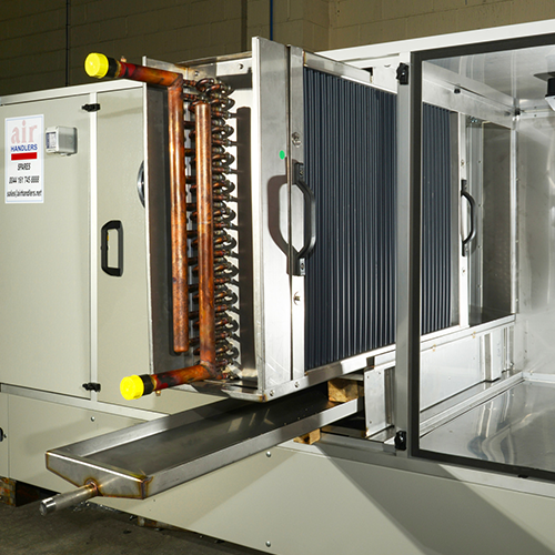 Removable cooling coil and drain tray to HTM-03
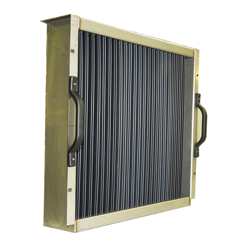 Removable HTM-03 eliminator module
Various humidifiers are used in NHS Trust Hospitals and all types will produce sterile steam, in the case of indirect steam/steam humidifiers (Spirax Sarco type).
The humidifier body will be attached to the casework and supported, distribution steam lances will be fitted in the humidifier section and supported.
The humidifier section length will be designed to ensure full diffusion of steam into the airflow, this is achieved by spreading the outlet nozzles in the lances in the humidifier section uniformly.
It may be required to fit multiple distribution lances in the humidifier section, to diffuse the steam correctly, Air Handlers Northern Ltd selection software automatically selects the correct distribution lance arrangement.
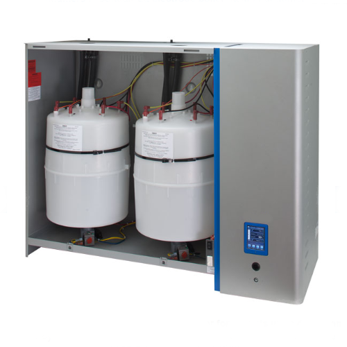
Another type of humidifier used in hospitals is the electrode boiler steam humidifier, this product can be fitted to the air handling unit casework or mounted remotely, in the case of unit mounted electrode boiler self-generating steam humidifiers, the distribution lance is connected to the humidifier unit by flexible steam hose or copper pipework. In the case of remote mounted humidifier unit(s) then the contractor will need to fit the humidifier and pipework to connect the distribution lance.
Electrode self-generating steam boiler humidifiers produce sterile steam and utilise a cylinder to reduce or eliminate minerals carried in the towns feed water, the minerals/limescale collected in the cylinder is periodically flushed to drain as build up happens, in the latest self-generating humidifiers on the market, this build up is monitored by its control system and is automatically flushed to drain.
It must also be noted that good mineral control will prevent excessive scale build up, thus increasing significantly the cylinder life.
A third humidifier system used on hospital air handling units is the self-generating resistive humidifier. This type of humidifier does not use disposable boiling cylinders which reduces maintenance and cylinder replacement cost.
This product utilises a scale in built management system, scale that forms on the heating element breaks off under normal operation and falls into the externally located scale collection tank. A push button will cool down the unit so the collection tank can be emptied. Electrode steam boiler and resistive self-generating humidifiers have a range of 5/110 kg/hr steam production in the case of large moisture humidifiers requirements above the largest standard product range, multiple of humidification are used and controlled via inbuilt modulating controllers and sensors, additional distribution lances will need to be installed to give the correct diffusion of moisture.
Humidifier sections will always be positioned after the fan section to ensure that it is under positive pressure. Modular eliminators are fitted at the terminal end of the section and removable for cleaning.
The section will have a full-sized access door for cleaning the drain tray, steam distribution lances and removable eliminators. The interior of the humidifier section, drain tray and eliminator casework also holding frame are constructed from stainless steel. The internals of the humidifier section will have smooth surfaces with no areas where moisture/dirt can collect.
The drain tray which is constructed from stainless steel with a minimum 20:1 slope to ensure the tray empties correctly and extends under the eliminators. The trap and drainage system will be under positive pressure. To comply with the rigorous hygiene standard required for Medsafe air handling units the entire humidifier section is stainless steel lined. The access door will have a viewing port fitted with an LED low voltage bulkhead light to illuminate the section to view the operation of the distribution lances.
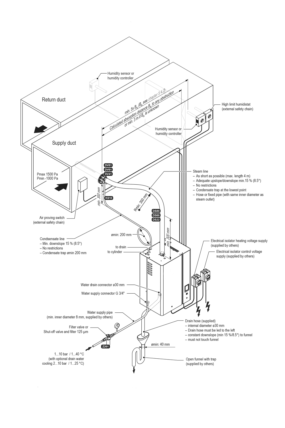 Typical ductwork installed humidifier
Final Filtration – High grade filters
Final filtration can be located either in the air handling unit or terminal filtration devices in the room, operating table system, scanning equipment etc. it is normal depending on the classification of the area or equipment that HEPA filters are used with high efficiency particle resistance to
Grade 1 – E10 to E12
Grade 2 – H13 to H14 high efficiency particulate filters (HEPA)
Grade 3 – U15 to U17 ultra low particulate filters (ULPA)
Typical EPA & HEPA Filter Healthcare selections to BS EN1822 - (2019)
UCV Theatre – EPA E10 – 85% efficiency
– EPA E11 – 95% efficiency
Immunosuppressed
And Neutropenic patient – EPA E12 – 99.5% efficiency
Rooms & Wards – HEPA H13 – 99.95% efficiency
610x610 modules with half modules available. The HEPA filter modules are supported on a airtight rigid frame and the HEPA filters will be fitted to the frame with airtight seals and under positive pressure to press the filters against the seals.
For Healthcare Society’s (2018) SVHSoc.02 – ‘Change in air filter test and classification standards’
Final filters can be tested for airtightness with a D.O.P. test to confirm no leakage of the frame/filter modules has taken place.
The filter section will have an access door which will have a viewing port fitted with an LED low voltage bulkhead light to view the filter condition.
Filters on Medsafe air handling units are firmly secured to the holding frame with a quick release fixing system to allow user friendly filter change. If HEPA filters are used for extract systems requiring filtration from fume cupboards, contaminated dirty areas, then a safe change system must be employed to keep the maintenance operative protected.
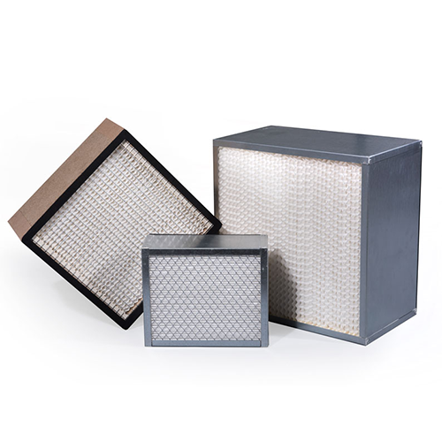 Typical HEPA filters
To comply with HTM-03 requirements for isolation or the AHU, motorised shut off dampers have to be fitted within the intake of the unit, this damper is to be airtight 2% leakage quality with blade and edge seals also have an aerofoil blade profile.
Medsafe units have an option at an additional cost for an insulated blade damper offering higher protection from intake frost and mist conditions. Also the Medsafe range can be provided with a Joventa UK damper actuator.
Again to be in compliance with HTM-03 a discharge damper is fitted to the air handling unit for isolation, this damper has a manual quadrant clearly marked open/closed, the damper is of similar construction to the inlet damper.
General Access
Access to components and for cleaning and replacement is an essential requirement to HTM-03.
The floors inside all access sections are of sufficient strength to support maintenance operatives without flexing, also general access doors are full size height and 500mm wide with the required viewing ports and low voltage bulkhead lighting.
Where access sections contain components like cooling coils, humidifiers then they will be fully stainless steel lined to allow cleaning with smooth internal surfaces.
With double deck air handling units where the top deck is higher than acceptable height and will need access equipment to look through the top deck viewing port, then the viewing port will be positioned near the bottom of the top deck section of the air handling unit.
Attenuators
Sound attenuators can be held within the air handling unit or supplied loose to bolt on the inlet/outlet of the unit. If attenuators are sited in the ductwork away from the air handling unit, then care must be taken by acoustic insulation to prevent noise flanking the attenuator.
Attenuator splitters should be constructed from universal mineral wool slab with a minimum density of 45kg/m3, the material will be scrim faced to prevent fibre migration and be odourless, rot proof, non-hygroscopic. This material will not sustain vermin and will not encourage the growth of fungi, mould or bacteria.
The absorbent faced slab will be wrapped in 125-micron thickness Melinex to prevent any moisture ingress. The completed attenuator slab is then encased in a white coated sheet metal casing.
Attenuator splitters are spaced within the air handling unit casework or duct casing to offer the correct insertion loss required. Access will be made on all Medsafe ait handling units up and downstream.
Baseframes
Drainage is a major requirement to prevent legionella bacteria growth, the most important requirements are:
- Drainage of all drain trays within the air handling unit.
- Correct trap design and sizing with a minimum clear air gap of at least 15mm above the unrestricted spill level.
- Borosilicate glass traps must be provided by the contractor, the trap must incorporate couplings to allow removal for cleaning.
- All traps will be under positive pressure with a depth sized to suite the maximum static pressure on the trap.
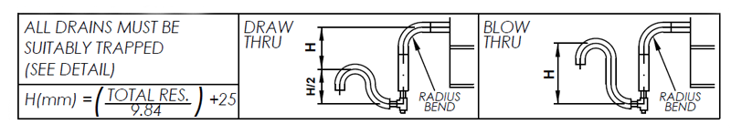 Standard trap information supplied on Air Handlers Northern drawings.
- Drainage pipework installed by the contractor should be a minimum diameter of 22mm and have a fall of at least 1:60.
Base frames will generally be a minimum height of 300mm to accommodate the correct trap and drainage sizing. Details of recommended trap dimensions for Medsafe air handling units are shown on all drawings issued to the contractor and included in the operating and maintenance manuals.
Where Medsafe air handling units are split for delivery into sections, the section will have a complete baseframe which will be under the perimeter of each section.
Baseframes are manufactured to support the weight of lifting, manoeuvring, and the internal components and maintenance operatives.
To ensure baseframes are level on the plantroom floor or upstand plinth, care must be taken by the contractor that they are level and do not need levelling shims.
The Construction of Medsafe air handling unit casework complies with EN 1886 and EN 13053 and HTM-03 2021.
Frameworks are constructed from 50mm pentapost anodised aluminium profile, with die cast powder coated aluminium corners, captive fixed to form a frame. Intermediate mullions are used to construct component compartments, access doors and inlets/outlets.
Panels will be flush mounted into the frame with neoprene seals to offer airtight sealing, fixed panels will be securely fixed from the inside with cadmium plated fixings, access sections will have hinged and lockable doors.
The thickness of the panels will be 50mm (mean) and manufactured from an outer skin of plastisol plastic coated steel, with a galvanised sheet steel internal skin, various thermal and acoustic insulation composites are sandwiched between the two skins.
Casing Classification (EN 1886)
| Leakage | L2 (DW143 Class B) | |
| Deflection | D2 | |
| Filter bypass | PM10 | 6% maximum |
| PM2.5 | 4% maximum | |
| PM2.5 | 2% maximum | |
| F8 | 1% maximum | |
| F9 | 0.5% maximum | |
| Thermal Transmission | T2 | |
| Thermal Bonding | T2 | |
Acoustic Insulated Casework
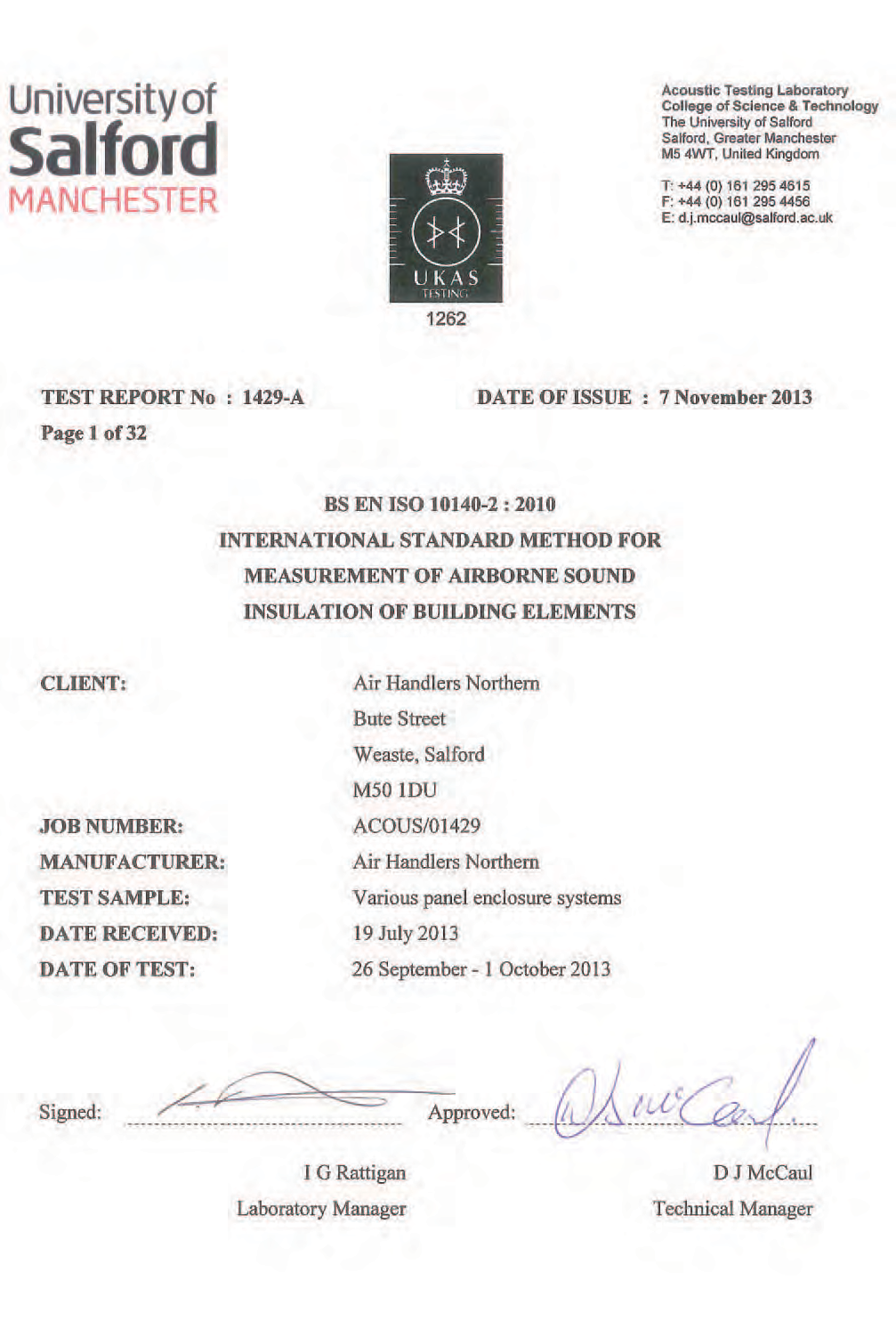
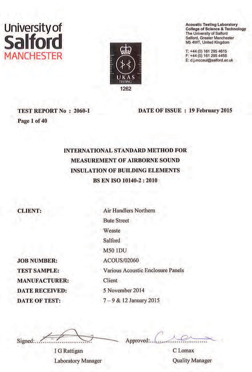
In the case of noise sensitive applications triple and quadruple skin panels are available with different thermal/acoustic composite modules. All composite panels have been tested by Salford University Acoustic Laboratory who are UKAS accredited and are certified to BS EN ISO 10140-2 (2010) Reports No’s 1429 & 2060.
To enhance the acoustic sound reduction from the frame Acoustishield high density sound insulation is fitted into the frame offering good SRI values.
Below are listed the options for:-
Standard Panels – double skin universal slab lined (50mm thick)
| Freq Hz | 63 | 125 | 250 | 500 | 1K | 2k | 4k | 8k |
| Power loss db | 16 | 17 | 27 | 38 | 39 | 34 | 32 | 40 |
Triple skin Panels – triple skin with acoustic composite lined
| Freq Hz | 63 | 125 | 250 | 500 | 1K | 2k | 4k | 8k |
| Power loss db | 21.7 | 24.2 | 36.4 | 37.3 | 37.6 | 33.4 | 35.7 | 41.5 |
Quadruple skin Panels – quadruple skin with acoustic composite lined
| Freq Hz | 63 | 125 | 250 | 500 | 1K | 2k | 4k | 8k |
| Power loss db | 24.1 | 36.6 | 34.7 | 39.8 | 40.7 | 37.8 | 39.7 | 43.7 |
Where transmitted noise from the air handling plant is in noise sensitive areas, then a higher sound proofed casework will be needed offering greater sound reduction index values.
For further information please visit : Air handling unit acoustic insulation performance tests.
Reports NOS 1429/2060
Acoustic tests to BS EN ISO 10140-2 (2010) and carried out at Salford university test laboratory.
Fresh / Out Exhaust Air termination
Fresh air intakes and exhaust air outlets must be separated as to eliminate any possibility of re circulation of exhausted extract air. It is recommended that fresh air and exhaust air terminals are 4 metres apart.
All Medsafe Air handling units having fresh air or exhaust air louvres, cowl louvres or cowls will be full faced on the inlet or outlet. Louvres and cowls will have bird/insect screens over the full face.
Recommended face velocities of intake and exhaust louvres and cowls are: -
- Intake air terminals 2.5 m/sec
- Exhaust air terminal 4.0m/sec
Both louvres and cowls will have a depth and profile to not allow any ingress of water during operation. When the air handling unit is not in operation and the inlet/exhaust dampers are closed, there must be no water or mist ingress.
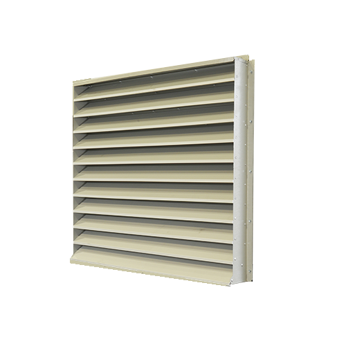 Typical Louvre
Where hospitals are located near airports and odour emitting areas, the use of activated carbon filters may be required.
Activated filter sections will be positioned directly after the pre filter to remove particles that will increase the carbon media life. Combined panel/carbon filters are an available alternative to activated tray type carbon filters, also to increase dust loading capacity bag type combined panel/carbon filters are available.
Standard activated carbon filter sections contain tray form panels which have activated carbon pellets held within the trays. The trays are arranged in a ‘V’ form horizontal arrangement to achieve a dwell time on the media of 0.25 seconds, which will remove a wide range of odours, irritants, toxic and corrosive gases, aviation fuel in the atmosphere. The carbon pellets act as an absorbent.
The activated carbon pellets do not filter particles or dust, they are retained on fine mesh trays to prevent carbon media migration. Carbon media can be cleaned in the trays by vacuum, this is recommended on a regular basis. Activated media replacement is recommended on a yearly basis.
 Tray form activated carbon panels side withdrawal
 Vee form rigid carbon filter module
Medsafe air handling units can be equipped with UV lamps contained within the casework. Ultraviolet light will offer effective protection against:
- Bacteria, Viruses and Germs
- Control other allergens
- Remove volatile organic compounds
- Reduces Smells and odours
- Maintains cleaner AHU internals
- Combined with other arrestance filtration can offer a very hygeinic environment
- Implementation of ERP 2018 on energy recovery devices
- Specific fan power ERP compliance.
- Access to components for cleaning/hygiene as designated in HTM-03.
- Coil and filter velocity compliance to HTM-03 and specific fan power limitations.
- Flat pack AHU site build.
- On site Bolting of AHU sections
- Site leakage testing
- Controls commissioning
- Component commissioning
- Performance test reports and certification.
- Site inspection of existing air handling units with condition report.
The UV lamps disinfect the air that we breath on a continuous basis, ultraviolet light disrupts the DNA of the germs and virus which loses the capability to multiply. The regeneration of germs etc are reduced to a minimum. Ultraviolet light rays provide the ideal method of reducing bacteria and virus spreading in a health care and hygienic environment.
Ultraviolet light in the band C range is commonly known as ultraviolet germicidal irradiation (UVGI). To provide effective destruction of harmful viruses, bacteria, spores etc the correct effective dosage of UVC must be applied, which will be high intensity UVC note that our UVC solutions inactivate Sars-Cov2 the Virus causing COVID-19.
On the completion of the air handling unit installation it is the NHS Trusts responsibility to validate the air handling unit, drainage requirement, ductwork attached installation meets HTM-03. It is also commonplace that a validation authorised engineer (AE(V)) inspects the air handling unit at the factory before delivery. The validation engineer can also be defined as a competent person (ventilation).
Derogation
Replacing existing old air handling installations is the most challenging of hospital engineering works, space is the most difficult of issues, as a replacement, air handling units will be considerably larger than its existing ancestor.
The reasons for this large increase in size is as follows: -
It may not be possible to replace the existing air handling unit plant with a fully compliant replacement without major building modifications to relocate the air handling plant.
In the case of non-compliance to HTM-03 and ERP laws a process of derogation is required by the NHS trust instructing the main contractor that none compliance is to be adopted along with a written statement, clearly stating why the derogation is being employed and exactly what is being derogated in the design and compliance.
It must be noted that HTM-03 is a guidance document similar to the CIBSE guide. But ERP directives are law which are overseen by the department of weights and measures in the UK.
Air Handlers Northern Ltd will only comply with HTM-03 and ERP directives unless we have a full derogation in writing from the NHS trust or main contractor.
Air Handlers Northern Ltd has a qualified site service team which has carried out hundreds of hospital air handling unit upgrades to meet current NHS specifications requirements.
Our site services division can also replace damaged and worn out components, as well as supply spare parts.
We have controls and refrigeration engineer(s) in the site services department to offer a complete service and maintenance package. Factory testing in our testing area is also available for leakage, airflow and breakout noise. This can be witnessed tested by arrangement.
Other services offered by air handlers site services are: -
For further information and advice contact our sales office on (+44) 0161 745 8888
Key Data
Alternative to F Gas
The Envirofresh and Freshcool are available with environmentally friendly Hydrocarbon refrigerant. Combine with VRV or chilled water systems to reduce F gas volumes.
For more information or professional advice and assistance please contact us on 0161 745 8888